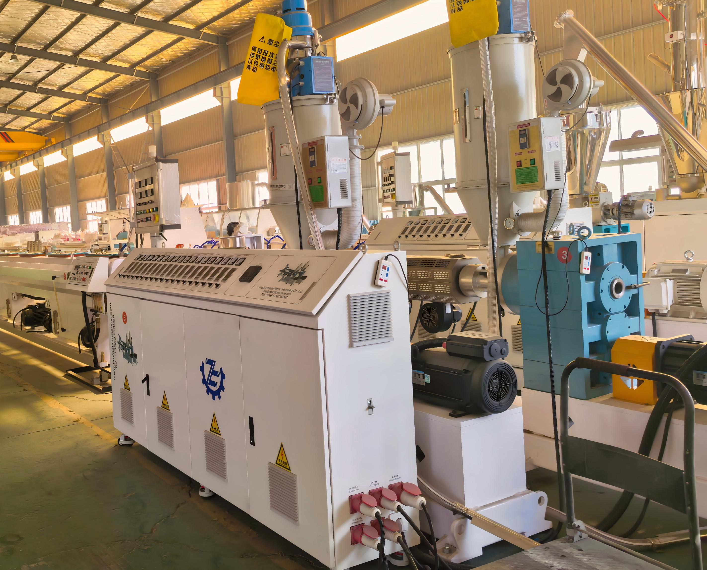

Wood Plastic Machine Factory Essentials for Efficient Production Lines
2026-09-08
Ask any production manager at a WPC plant what keeps them up at night, and the answer rarely changes: inconsistent output, unexpected downtime, and machinery that fights rather than flows. The right wood plastic machine factory setup changes that calculus. From screw design to cooling bed alignment, small choices ripple through every kilogram of profile you extrude. Here’s what actually moves the needle—and where Yongte fits into that picture.
Raw Material Prep That Prevents Extruder Surges
Surges usually trace back to inconsistent feed density, not the screw itself. When regrind and virgin pellets are loaded without controlling size distribution, the flights alternate between starved and flooded. A simple fix is to screen regrind through a 3/16-inch mesh and meter it into the virgin stream at a steady ratio—often 20–30% by weight—rather than letting operators eyeball the mix.
Moisture swings are another quiet trigger. Even small humidity changes in the hopper alter how material slips or sticks in the feed throat. Keeping hygroscopic resins on a desiccant dryer and storing non-hygroscopic materials in covered bins at a stable ambient temperature removes that friction variability. You don't need perfect dryness; you need the screw to see the same conditions hour after hour.
Feeding consistency also fails when fines or long strands bridge in the hopper. A vibratory feeder or a slow-turning vertical agitator prevents rat-holing before it creates a feed gap. Add a low-level alarm so the line never runs dry mid-shift. Once the material entering the throat is steady and boring, melt pressure stabilizes and the surging stops.
Barrel Zone Tuning for Consistent Melt Pressure
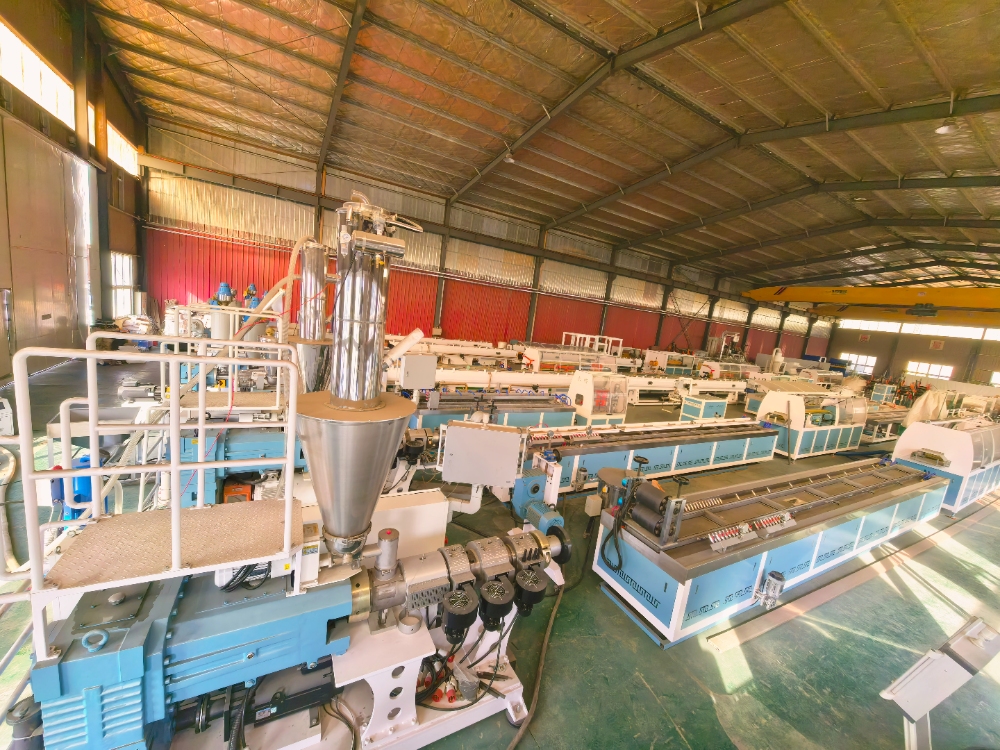
Barrel temperature zones rarely behave the way their setpoints suggest. The rear zone feeds solids, the middle zones handle compression and melting, and the front zone trims viscosity before the check ring or die. If any one of these zones drifts too far from the resin's actual melt window, the screw has to work harder, and melt pressure starts to oscillate. A rear zone set too hot can cause premature melting and erratic feeding, while a cold front zone often shows up as pressure spikes right at the nozzle.
Tuning for steadier pressure means watching the transducer trace instead of relying on barrel setpoints alone. Move one zone at a time by no more than a few degrees, then let the machine settle for several cycles before judging the result. If pressure dips at the end of recovery, the metering section may be running too warm. If the trace shows regular surging during plastication, the feed throat or rear zone often needs a slight reduction. Keep notes on each change and the pressure response so the profile stays repeatable across materials and shifts.
Once the zones are balanced, the payoff shows up in shot consistency and reduced scrap. A flatter pressure trace during injection and hold usually means the melt is arriving at the same viscosity every cycle. In practice, technicians find that small, patient zone adjustments cut down on short shots and flash caused by pressure swings, and the process becomes far easier to start up after a cold barrel or a material change.
Screw and Barrel Wear Signs You Can't Ignore
Uneven melt temperature is one of the earliest red flags. When the screw flight and barrel wall start losing their original clearance, shear heating changes in ways that no amount of heater band adjustment can fully mask. You may notice the melt stream arriving at the die with hot and cold striations, or the pressure readout drifting even though your settings haven't moved. Operators often blame the thermocouple first, but if replacing probes doesn't settle the fluctuation, the geometry of the screw is quietly telling you something is wrong.
Another sign is a gradual drop in throughput that isn't explained by feedstock changes or screen pack buildup. As the screw root diameter wears, the volumetric displacement shrinks, and the barrel's polished bore develops scoring that creates a backflow channel. The machine will work harder to hit the same rpm, and you might hear a metallic groan from the drive section under load. If you track output per kilowatt-hour over a few weeks, the efficiency curve bends downward in a way that's hard to blame on ambient conditions.
Pay attention to what comes out of the vent or vacuum port. A worn screw and barrel pair often starts pulling air or volatiles differently, leading to splay, silver streaks, or tiny black specks in the finished part. Those specks aren't always degraded resin; they can be microscopic metal fines or charred polymer trapped in the new gaps. When you see contamination that survives a thorough purging and a clean screen change, it's worth pulling the screw for an inspection before the wear turns into a catastrophic barrel scoring event.
Die Head Adjustments for Uniform Wall Thickness
Getting consistent wall thickness out of an extrusion die rarely happens by accident. The die head is where melt distribution gets finalized, and even a slight misalignment between the mandrel and the die bushing will show up as a thin side or a heavy side on the finished product. Operators often chase downstream variables like haul-off speed or cooling water temperature before checking the head itself, but those adjustments only mask the real issue. A die that isn’t centered properly will produce a wall that varies not just in thickness but also in orientation, meaning the thin spot might drift around the tube depending on melt pressure and temperature swings. So before touching anything else, confirm the die head is actually the source of the problem by cutting a short sample straight off the head, measuring it in four quadrants, and comparing those numbers to what the die geometry suggests.
The actual adjustment process usually comes down to a handful of bolts arranged around the die body. On most heads, loosening one side while tightening the opposite side shifts the internal mandrel relative to the outer ring. The trick is to make small moves—no more than a quarter turn at a time—and let the melt flow stabilize before measuring again. Some operators use a feeler gauge to check the annular gap directly when the head is cold, but that reading can change once the steel expands at operating temperature. A better approach is to work from the extrudate itself: measure the wall at the same marked point around the circumference after each adjustment, then plot those numbers against the bolt positions. That way you can see which bolt pair influences which part of the wall. It’s a slower method, but it avoids the common mistake of overtightening one side and creating a new thin spot ninety degrees away.
Once the wall looks uniform on a hand-cut sample, give the line a few minutes to settle and recheck with an ultrasonic gauge or a micrometer on a cooled section. Melt temperature shifts, screw speed changes, or even a dirty screen pack can nudge the distribution back off center, so treat the die head adjustment as a starting point rather than a one-time fix. If you find yourself correcting the same bolt every shift, the mandrel support or the bushing itself may be worn unevenly and worth pulling apart for inspection. For short runs, a quick centering pass is often enough, but for long production campaigns it pays to document each die position and the corresponding wall profile, so the next startup doesn’t start from scratch.
Inline Cooling and Sizing Without Warpage
Once the melt exits the die, the next few meters decide whether a profile stays straight or comes out with a slow curve. Inline cooling and sizing tackle that window directly. A vacuum sizer pulls the hot shape against chilled calibrators while water circulates through channels only a millimeter or two from the surface. That fast skin formation locks dimensions early, but the real trick is pulling heat out evenly from every side. If one face gets more spray than the other, the part sets at different rates and stores stress that shows up later as bow or twist.
Instead of relying on one fixed water temperature, many lines now use stepped cooling zones. The first tank runs warmer so the surface doesn't shock and crack; the second drops lower to build wall strength; a final soak zone lets the core cool slowly before cutting. Air wipes between tanks prevent cold water from dragging backward into the sizing area. Operators can tune the vacuum level, water flow, and spray pattern independently for each rail, which makes it possible to correct a slight drift before it becomes a full warp.
The payoff shows up at the cutoff saw. A profile that enters the puller straight and stays straight needs no post-forming straightening jig and wastes less material on bowed sections. Keeping the core temperature from lagging too far behind the skin is often the missing piece, since warpage frequently appears only after the part sits for a few hours. By giving the center enough time to normalize on the line, the finished part keeps its shape without extra handling.
Shift Checklists That Keep Changeovers Under an Hour
Most changeovers drag because people rely on memory instead of a written sequence that follows the physical flow of the line. Tape a laminated card to the machine that lists each step in the order a technician walks around it—power down, purge, swap dies, set first-off dimensions, torque check. Give every step a box next to the person's initials and a target minute mark. If the list has more than twelve steps, split it into two-person tasks and mark which hand-offs can happen in parallel.
The checklist only works if tools and replacement parts are staged before the last good part comes off. Dedicate a shadow board or a wheeled cart with labeled cutouts for the exact wrenches, collets, and fixtures that changeover needs. At the start of the shift, the outgoing operator signs off that the cart is restocked and that purge material is within arm's reach. Missing anything gets written on the whiteboard by the machine, not in an email, so the next crew sees it.
Time each hand-off rather than the whole changeover. Use a stopwatch function on the HMI or a simple magnetic timer stuck to the guard. After three changeovers, circle the two steps that took the longest and ask the crew what would remove ten minutes from each. Update the checklist only when a change sticks—otherwise you end up with a document nobody trusts. Keep the card in a plastic sleeve and replace it when the ink fades.
FAQ
Placing the extruder too far from the material mixing station creates long transfer paths. Keep blending, feeding, extrusion, cooling, and cutting in a straight or U-shaped flow so material moves forward without backtracking. That alone can cut handling time substantially.
The extruder's screw design usually matters more than motor size. A screw optimized for wood-plastic composites prevents surging and overheating, letting you run longer between cleanings. Pair it with a gravimetric feeder instead of volumetric to hold density consistent.
Dry wood flour or fiber to below 1% moisture before it enters the compounding stage, and use closed-loop conveying after drying. Even small moisture swings create surface roughness and weak spots, so install inline moisture sensors rather than relying only on lab checks.
Checking barrel and screw wear every 300 to 500 hours, not just when output drops. Wood-filled compounds are abrasive, so keeping a log of melt pressure at a fixed screw speed reveals wear trends early. Replace screens and breaker plates on a schedule instead of waiting for pressure spikes.
They dose color concentrates by hand or by timer. Gravimetric dosing of masterbatch tied to the main feed rate keeps the ratio stable even if output changes. Also pre-mixing pigments with a small portion of wood flour helps avoid streaking in the final profile.
The first cooling tank temperature. Overly cold water can shock the surface and lock in stress, causing bowing later. Use graduated cooling with the first tank around 60-70°C, then step down gradually, and keep water flow uniform across all sides of the profile.
Track kilograms of finished product per kilowatt-hour and per labor hour, not just line speed. A fast line that produces heavy scrap or needs constant operator adjustment may be less efficient than a slower, stable line. Weekly Pareto analysis of downtime reasons reveals the biggest losses.
A central dust system with hoods at cutting and milling points protects both equipment and workers. Fine wood dust can settle on sensors and cause feed errors, so regular duct cleaning and proper air velocity prevent buildup and reduce fire risk, keeping the line running safely.
Conclusion
Running a wood plastic composite extrusion line without careful raw material handling is asking for trouble. Moisture swings or inconsistent particle sizes in the wood flour will back up into the extruder as surging, and you'll see it immediately in melt pressure spikes. The fix usually starts at the feed throat, not the control panel. Once you've got a steady feed, barrel zone tuning becomes the next lever. Many operators chase melt pressure by overcorrecting a single zone, but balanced setpoints across all zones keep the viscosity stable and reduce motor load swings. At the same time, don't skip screw and barrel wear checks just because the line is running. A worn screw builds up backpressure slowly, and by the time the product goes out of spec, you've already lost hours of production. Regular measurement of flight clearances and barrel ID will catch trouble before it shows up as black specks or dimensional drift.
Downstream, the die head can make or break wall thickness consistency. Most operators adjust the die bolts too aggressively, creating thin spots that only appear after cooling. Instead, make small, logged changes and wait for the effect to propagate through the cooling tank. Inline cooling and sizing need attention too—if the water temperature or vacuum calibration drifts, the profile will bow or twist under residual stress. A well-designed sizing sleeve with staged cooling zones prevents warpage without slowing the line. Finally, shift changeovers are where efficiency dies if you don't have a checklist that actually gets used. The best factories keep changeover tools staged, preheat the die on a cart, and assign one person to document each step. That keeps the switch under an hour, and the next shift starts with a warm, stable line instead of troubleshooting someone else's mess.
Contact Us
Contact Person: Ms Qin
Email: [email protected]
Tel/WhatsApp: 8613583233866
Website: https://www.yongteplast.com