

Top H Beam Shot Blasting Machine Company Delivering Consistent Surface Quality
2026-08-29
A consistent surface profile on H beams rarely happens by accident. It takes precise control over blast angle, abrasive flow, and machine timing—areas where PuHua has focused its engineering for years. Here’s what to expect from a supplier that treats repeatable shot blasting quality as the standard, not the exception.
Why Standard Blasting Falls Short on Long H Beam Profiles
Standard blasting setups, with their fixed nozzle angles and uniform throw distances, struggle to maintain consistent surface profiles across the full length of an H beam. The flanges and web create deep shadow zones where abrasive ricochet loses energy, leaving mill scale and rust pockets that a quick visual check can miss. On beams longer than twelve meters, even minor variations in conveyor speed or nozzle wear translate into noticeable streaks along the edges.
Another shortfall shows up at the inside corners where the web meets each flange. These tight radii trap spent abrasive and dust, creating a cushion that absorbs impact before fresh media ever reaches the steel. Operators often compensate by slowing the line or raising blast pressure, but that only leads to overblasting on the outer faces while the critical weld-prep areas still underperform.
Long profiles also exaggerate the problem of heat input from high-energy blasting. Thin webs can bow or twist when one side receives more aggressive treatment than the other, especially if the beam sits slightly off-center in the cabinet. The result is not just poor anchor pattern uniformity, but dimensional drift that creates downstream fit-up headaches in structural fabrication.
The Link Between Blast Wheel Position and Surface Evenness
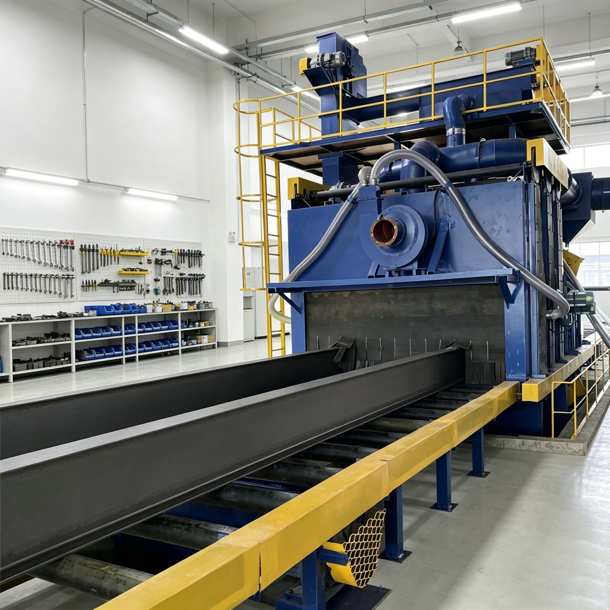
A blast wheel's mounting point relative to the workpiece does more than set the working distance—it fixes the impact footprint and the spread angle of the abrasive stream. When the wheel sits too close or is angled steeply into the surface, the center of the blast pattern receives a denser, faster particle flow, leaving the edges under-treated. This uneven energy distribution shows up as a wavy surface profile, with roughness peaks that drift from one side of the plate to the other.
Lateral offset and tilt create a different problem. If the wheel is shifted just a few millimeters off the feed line, the abrasive strikes the leading or trailing edge of the strip at an oblique angle, which lowers effective impact force and smears the pattern. Rotation direction relative to part travel also matters: a wheel throwing with the feed direction can pile abrasive into a narrow band, while counter-rotation spreads the overlap more evenly. Operators often chase this by increasing abrasive flow, but that only deepens the hot spots instead of flattening the coverage.
The real fix is to map the blast pattern against the actual surface response. Move the wheel in small increments, run a sample, then measure roughness or peak count every 100–150 mm across the width. Adjusting the control cage timing or tilting the wheel housing by half a degree can shift the effective impact zone enough to cancel a persistent ridge. Evenness is not a product of more power—it comes from placing the wheel so that the abrasive spends the same amount of energy at every point of the pass.
How a Dedicated H Beam Machine Avoids Over-Processing Edges
A dedicated H beam machine is built with tooling that matches the beam's profile exactly. Instead of relying on a generic cutting head, it uses purpose shaped rollers and guides that ride along the web and flanges without wandering. This fixed geometry means the machine never drifts into areas that don't need work, so the edge stays untouched after the initial pass.
The clamping system on these machines also plays a big role. Because the beam is held firmly at multiple points along its length, there is no flex or vibration during machining. That stability lets the operator set a very shallow removal depth and trust that the tool will follow the contour without skimming too much off the corner of the flange.
Finally, many dedicated H beam machines include a simple mechanical stop or a preset limit for depth of cut. Once the operator dials in the correct settings for a given beam size, the machine physically cannot move beyond that point. This hard stop prevents the common mistake of over-processing edges that happens when someone tries to use a multi-purpose mill for beam work.
Anchor Profile Uniformity Remains the Metric That Matters Most
In protective coatings work, surface preparation often gets reduced to a single number: the anchor profile depth. But that reading alone can mislead. A profile that measures 75 microns in one spot and 40 microns just a few centimeters away creates uneven mechanical bonding. The coating may look fine during application, yet premature failure is already written into the surface. Uniformity across the blast-cleaned area is what determines whether adhesion holds under thermal cycling, moisture ingress, or mechanical stress.
Contractors and inspectors naturally focus on the peaks because they are easy to capture with replica tape or stylus instruments. However, the valleys and the spacing between peaks matter just as much. When the profile is uniform, the coating can wet out consistently, minimizing entrapped air and thin spots over the ridges. If the profile is erratic, even a high average depth won't compensate for areas where the coating lacks a proper mechanical key.
The practical takeaway is to stop treating anchor profile as a pass/fail check based on a single average. Instead, map the surface at multiple points and pay attention to the spread of readings. A narrow distribution—regardless of the specific abrasive used—is a stronger predictor of long-term coating performance than a high peak count. That quiet consistency is what separates a surface that merely looks prepared from one that actually is.
Same Finish Beam After Beam Without Rework
A uniform finish on every beam starts well before the first float touches the surface. The mix has to stay within a narrow slump range, and the pour rate needs to match how fast the crew can work the edge forms. When those two stay steady, the surface closes up the same way each time, so there’s nothing to grind down or patch after the forms come off.
The real difference shows in the details that don’t get talked about much. Keeping the screed rails clean, running the vibrator at the same depth on every lift, and resisting the urge to add water when the concrete starts to tighten—those habits carry the finish from one beam to the next. Once the timing becomes second nature, the sheen and texture repeat without a second pass.
Most rework traces back to small drift: a blade angle changed slightly, a section left too long before the next pass, or a cold joint forming where the placement paused. Locking the sequence beam after beam turns all of that into a routine. The next pour should look like the last one not because anyone got lucky, but because the steps were the same all the way through.
What a Specialist Company Checks Before Shipping Your Machine
A specialist company doesn't just bolt your machine to a pallet and call it done. Before anything leaves the floor, it's run through a full-load cycle until it reaches normal operating temperature, not just a quick cold start. The technician listens for unusual noise, feels for abnormal vibration, and watches temperature and pressure gauges during a sustained run. Every safety interlock, emergency stop, and guard switch is tripped deliberately to confirm it works as intended, not just assumed to be wired correctly.
After the mechanical and safety checks, the machine's settings are verified against the order specification. Calibration is compared to a reference standard, and the exact values are recorded on a shipping log rather than left to memory. Customer-specific parameters, such as speed limits, tool offsets, or recipe settings, are loaded and then rechecked after a power cycle. The specialist also confirms the firmware or software revision matches what was quoted, since a mismatch here can cause days of downtime at the customer's site.
Finally, there's a physical inspection that goes beyond wiping off fingerprints. Critical fasteners are spot-checked with a torque wrench, fluid levels are topped to the specified marks, and hoses or cables are inspected for any sign of chafing from test runs. Consumables like filters and seals are either replaced or clearly labeled with remaining life. Only after the machine is clean, dry, and protected with the right anti-corrosion treatment does it get crated, with desiccant packs and tilt indicators added to the packaging so you know exactly how it was handled in transit.
FAQ
Their machines use a rotating work carousel and multiple angled turbines that fire abrasive at the web, flanges, and fillet areas simultaneously. This eliminates shadow zones that often occur between the flange and web, where rust and mill scale tend to hide. The nozzle positions are calibrated per beam height, so a 200 mm beam receives the same impact density as a 900 mm beam without manual retuning.
They rely on low-heat abrasive types and a controlled feed rate, both tied to a laser-based thickness scanner mounted before the blast cabinet. The system automatically reduces blast pressure and travel speed when it detects flange thickness below 12 mm. Additionally, a spring-loaded roller conveyor keeps the beam stable without clamping force.
Inconsistent blasting leaves patches of mill scale or pitting that cause coating adhesion failures within months. For galvanizing, residual rust leads to bare spots after the zinc bath. Their machines target a Sa 2.5 finish across the entire surface, including weld seams, and include a post-blast air knife that removes dust before the beam exits.
Daily checks include abrasive level, turbine amperage, and seal wear on the cabinet doors. Every 40 operating hours, they advise removing the abrasive, screening it, and refilling to keep particle size consistent. Blades and impellers should be rotated every 300 hours, with a full turbine rebuild at 1500 hours. The dust collector filters need compressed air pulse cleaning daily and bag replacement after 2000 hours.
Yes, their standard line accepts beam heights from 100 mm to 1000 mm and lengths up to 18 meters. The inlet and outlet conveyors are height-adjustable via hydraulic lifts, and the blast turbine angles shift through a memory-based PLC with presets for common beam sizes. Changeover takes under 10 minutes and does not require tooling changes.
They should ask about abrasive coverage on the inside fillet where the web meets the flange—many units only blast the outer surfaces. Also check the turbine power per meter of beam width, not just total motor rating. A good benchmark is at least 15 kW per turbine per meter of beam height. Request a sample blasting test with a section of real beam, and measure surface profile in three zones: web center, flange edge, and weld toe.
Their recovery system uses a screw conveyor under the blast cabinet paired with a bucket elevator that separates reusable abrasive from fines via an air wash separator. The dust collector has a pulse-jet design with PTFE-coated bags that resist moisture from humid environments. A rotary valve at the hopper prevents air leakage that would reduce suction. This setup keeps dust emissions below 5 mg/m³, well under most plant limits.
Conclusion
Long H beam sections rarely respond well to equipment designed for plate or pipe. Standard blasting machines tend to position wheels for flat stock, so the inner flange faces and web-to-flange transitions get uneven exposure. On a 12-meter beam, that inconsistency compounds quickly — the edges near the flange tips can be struck too aggressively while the web centre receives only a light sweep. A specialist H beam machine addresses this by mapping wheel angles and travel speed to the actual profile geometry. When the blast wheels are aligned to cover the flange edges and inner corners without dwelling on the narrow tips, the surface evenness improves noticeably. This is not just about visual cleanliness; the anchor profile stays within a tighter band, which means later coating adhesion doesn't vary from one section to the next.
A dedicated supplier also tests for over-processing before the machine leaves the floor. They run sample beams through and check edge rounding, abrasive consumption, and residual dust collection on the web and flanges. The goal is to achieve the same finish on beam fifty as on beam one, without rework. Reputable companies verify blast wheel positions are locked after trial runs, check that abrasive valves and reclaim systems maintain a steady flow, and inspect the cabinet seals for leakage at the ends. Small oversights in these checks are what force fabricators to touch up surfaces later. A builder that insists on these pre-shipment checks is the one that can actually deliver consistent surface quality across long H beam profiles.
Contact Us
Contact Person: Bruce
Email: [email protected]
Tel/WhatsApp: +86 15166629468
Website: https://www.povalchina.com/