

Stainless Steel Casting Factory Techniques That Deliver Flawless Results
2026-11-16
Every stainless steel casting project begins with a critical question: how do you achieve a flawless finish without compromising structural integrity? At Supreme Machinery, we've spent years refining factory techniques that go beyond the standard pour-and-polish routine. From precision mold design to controlled cooling cycles, our approach eliminates micro-porosity and surface defects that plague lesser foundries. If you're tired of rework and rejects, this guide reveals the exact methods we use to deliver castings that meet zero-defect standards on every run.
Molten Metal Temperature Control That Eliminates Surface Defects
Surface defects in castings are rarely random. They usually start with a temperature swing in the holding furnace or transfer ladle. When molten metal cools unevenly, the first skin to form against the mold can re-melt or tear, leaving visible lap lines and cold shuts. The fix is not a higher setpoint—it is a tighter band around the pour temperature, maintained continuously from furnace to mold.
A practical approach pairs multi-point thermocouples with a feedback loop that adjusts induction or resistance heating before the metal ever reaches the pour spout. Instead of reacting to a drop that has already happened, the controller tracks heat loss during transfer and compensates in advance. This keeps the liquid within a 5–10 °F window, which is often enough to eliminate the microstructural differences that surface as rough patches or flow marks.
When temperature stays inside that narrow range, the metal fills thin sections before solidifying, and the mold coating releases cleanly without trapping oxides at the interface. Foundries that adopt this level of control typically see fewer rework hours and less reliance on heavy grinding to hide surface flaws. The result is a part that looks consistent from the first pour to the last, with no extra polishing needed.
Runner and Riser Designs Engineered for Laminar Flow
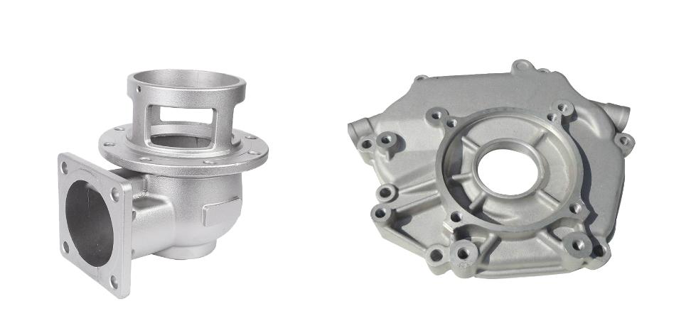
Molten metal travels through the gating system in a state that is often turbulent, but achieving a smooth, controlled fill depends heavily on how the runner and riser geometries are shaped. Runners with tapered cross-sections encourage the metal to slow gradually, preventing the sudden pressure drops that typically lead to air entrainment and oxide formation. By maintaining a constant cross-sectional area or a carefully calculated reduction along the flow path, the stream remains coherent, and the front advances with minimal splashing. This approach supports a laminar flow regime, where successive layers of metal fold over one another rather than tumbling chaotically into the cavity.
Riser placement and geometry also play a critical role in sustaining laminar conditions after the cavity begins to fill. A well-designed riser acts as a thermal and hydraulic buffer, drawing in the last portion of metal while allowing trapped gases and inclusions to rise away from the casting. Its neck should be sized to stay open long enough to feed shrinkage, but not so wide that it permits a sudden rush of metal that disrupts the established flow pattern. When risers are integrated with the runner system as part of a single, continuous channel, the entire network can be tuned to maintain a steady velocity profile from the sprue base to the farthest extremity of the mold.
Small geometric details, such as rounded corners at junctions and gradual transitions between sections, further suppress the onset of turbulence. Sharp edges or abrupt expansions create low-pressure zones and eddy currents that tear the metal stream apart. In contrast, smooth, blended contours distribute the kinetic energy evenly, allowing the metal to decelerate predictably as it approaches the ingate. Engineers often use flow simulation and water-model testing to refine these shapes, iterating until the fill time and velocity remain within a narrow laminar window across the entire casting. The result is a quieter pour, fewer surface defects, and a more uniform microstructure throughout the finished part.
Pouring Profiles Matched to Section Thickness
In casting design, the relationship between pouring speed and wall thickness rarely gets the attention it deserves. Thin sections demand a rapid initial fill to outpace premature solidification, yet that same aggressive flow wreaks havoc when it hits a thick boss or flange. Matching the pour profile to the local cross-section means the metal stream accelerates through narrow passages and deliberately slows as the cavity opens up, preventing both cold shuts and oxide entrapment in a single pour.
A practical way to visualize this is to trace the flow front as it advances through the mold. Where the section necks down, the profile should spike to maintain a coherent front; where it expands, the flow rate must taper to avoid jetting and air pockets. Foundries often achieve this by shaping the sprue and runner system rather than relying on a constant head pressure, with tapered runners that mirror the part's thickness transitions. The result is a pour that feels almost organic, adapting its energy to the geometry instead of forcing a one-size-fits-all velocity.
On the shop floor, this translates into measurable gains: fewer misruns in thin ribs, less shrinkage porosity in thick hubs, and a noticeable drop in fettling time. Skilled operators learn to read the fill pattern and adjust the ladle tilt or stopper rod position in real time, creating a pour profile that is as much about feel as it is about engineering data. When the profile matches the section thickness, the casting starts to behave less like a compromise and more like a deliberate, controlled solidification sequence.
Solidification Timing to Stop Porosity Before It Starts
Porosity rarely appears out of nowhere. It forms in the brief interval when a metal transitions from fully liquid to a solid network of grains. If solidification happens too quickly near the end of filling, dissolved gases cannot escape and shrinkage cannot draw liquid from the remaining melt, so voids become locked into the structure. Slowing the solidification front just enough—especially in the mushy zone—gives gas bubbles time to float out and allows feed metal to reach areas that would otherwise starve.
The practical lever is not total casting time but the local solidification rate at the last points to freeze. Lowering mold temperature a few degrees, adjusting alloy composition to widen the freezing range, or repositioning risers and chills can change the timing without extending the whole cycle. For instance, in thin-wall aluminum castings, a slightly delayed solidification near gate areas can reduce microporosity even when overall pour time stays the same.
Thermal analysis makes this controllable. By plotting cooling curves at critical sections, foundry teams can see exactly when solidification starts and ends, then match those timings to where porosity appears in cut-ups. Adjusting that window—often by only a second or two—can eliminate a defect that would otherwise require impregnation or scrap. The goal is to manage the order and pace of freezing before the first void forms, not to repair it afterward.
Digital Radiography Calibrated for Thin-Walled Castings
Digital radiography for thin-walled castings demands more than a simple exposure adjustment. The rapid attenuation changes across a few millimetres of metal create a narrow latitude where useful contrast can be pulled from the detector. Tuning the system to the specific alloy and wall thickness—often down to 1.5 mm or less—starts with a physical step wedge rather than a software preset. Each step is imaged at the same source-to-detector distance that will be used on the actual part, and the resulting grey values are checked against a known thickness curve. This keeps the calibration tied to the geometry that the production line will actually see.
Once the baseline curve is established, the calibration moves into detector normalisation. Flat-field correction removes pixel-to-pixel gain variation that can mimic porosity in a light casting. Bad pixels are mapped out before any part is inspected, because a single drop-out can easily be mistaken for a small gas cavity. The tube voltage is then pushed just high enough to penetrate the thickest rib but not so high that the thinnest web washes out; for aluminium alloys this often falls between 70 and 120 kV, depending on section changes. Each change in source, plate, or filtration triggers a fresh calibration rather than a minor tweak.
The final stage is verification against known discontinuities. A reference casting with drilled holes or embedded tungsten wires is radiographed under the calibrated conditions, and the operator checks that the smallest required flaw—typically 1% to 2% of wall thickness—remains visible at the edge of the image. If the wire or hole disappears, the detector gain or the contrast-to-noise ratio is adjusted and the step wedge is re-imaged. This loop of step wedge, flat-field, and reference part is what turns a standard digital setup into a reliable gauge for thin-walled work.
Finishing Steps That Restore Corrosion Resistance
Once stainless steel has been cut, welded, or ground, the surface layer loses its natural chromium oxide film. Simply exposing the part to air helps somewhat, but that’s rarely enough in harsh environments. A proper restoration routine starts with removing heat tint, embedded iron, and other contaminants. Mechanical methods like abrasive blasting or using clean stainless wire brushes can take off visible scale, yet they won’t rebuild the passive layer on their own.
Chemical finishing steps do the real work. Pickling with a nitric-hydrofluoric acid blend dissolves oxide scale and free iron, leaving a clean surface. After thorough rinsing with deionized water, passivation in nitric acid or citric acid encourages the chromium oxide layer to re-form quickly and evenly. For parts that demand maximum corrosion resistance, electropolishing can further smooth the surface and remove microscopic contaminants. The sequence matters just as much as the chemicals—skipping a rinse or using a contaminated brush can undo the entire restoration.
FAQ
Stainless steel shrinks more than carbon steel and tends to solidify quickly, so a poorly placed gate can starve the casting before it fills thin sections. Foundries that get consistent results often use tapered sprue wells and multiple ingates positioned to feed the heaviest sections first while keeping turbulence low. Without that balance, you see cold shuts or trapped slag that no amount of finishing will fix.
Porosity in thin walls usually comes from trapped gas or premature freezing. A lot of shops rely on vacuum-assisted pouring for sections under 4 mm, plus a mold wash that creates a reducing atmosphere. The metal is tapped slightly hotter than standard, but not so hot that it picks up hydrogen from humidity. Riser placement gets trickier because there is no mass to feed from, so chills are often embedded in the shell to direct solidification back toward the gate.
Stainless grades like 316 or duplex have narrow pouring windows and react with oxygen fast. Superheat must be held within 30 to 50 degrees Fahrenheit of the target or you get either misruns or excessive scale. Induction furnaces with continuous thermocouple feedback help, but experienced pourers also watch the color and fluidity of the stream. A ten-second delay at the ladle can change the oxide film enough to ruin surface quality.
The ceramic shell is what actually touches the metal, so its inner layer controls the final surface. Zircon flour prime coats give a smoother finish than fused silica, but they cost more and need careful drying between dips. Many factories use a two-coat prime system with controlled humidity to prevent cracking. If the shell isn't fully cured, steam from the wax or moisture creates gas defects that look like pinholes.
Austenitic grades need solution annealing to dissolve carbides and restore corrosion resistance, while martensitic grades require a quench and temper sequence. The exact soak time depends on section thickness, but a common mistake is holding parts too long and causing grain growth. Modern furnaces ramp in stages and use protective atmospheres to limit scaling. Some foundries also do a sub-zero treatment after hardening to stabilize retained austenite.
Yes, but it depends on how predictable the shrinkage is. With a well-characterized wax and shell system, tolerances of plus or minus five thousandths of an inch per inch are realistic, so leaving twenty to thirty thousandths stock is enough for most features. That means less machining time and less chance of cutting through the corrosion-resistant skin. It requires regular dimensional audits because a change in wax supplier or room temperature can shift the pattern size.
Radiographic testing is the standard for internal voids, but it's expensive and not every part needs it. For critical stainless castings, liquid penetrant inspection picks up surface cracks down to a few microns, while ultrasonic testing can find inclusions below the surface. Some factories also use CT scanning on first articles to map porosity in complex cores. The key is matching the method to the failure risk, not just checking a box on a report.
Conclusion
Precision in stainless steel casting starts long before the pour. Foundries chasing flawless results obsess over molten metal temperature, holding it in a narrow band that prevents cold shuts and surface veining. But heat alone is not enough—runner and riser layouts are cut to encourage laminar flow, so the alloy glides into the cavity without turbulence that traps oxides. Pouring speed then shifts with wall thickness: thin sections get a faster, more assertive stream to fill before freezing, while heavy sections are fed slowly to avoid erosion and air entrainment. This rhythm carries into solidification, where chills and insulation are placed to steer the freeze front from thin to thick, starving porosity before it can nucleate.
Verification separates a good pour from a guaranteed one. Digital radiography tuned for thin-walled stainless components catches micro-shrink and inclusions that conventional film might blur, giving inspectors a true map of internal soundness. Then the last step matters just as much as the first: finishing processes such as passivation, mechanical polishing, and controlled pickling remove surface contaminants and restore the passive chromium oxide layer. Without that, even a perfectly cast part can lose its corrosion resistance in service. Together, these techniques form a chain where each link—heat, flow, timing, imaging, and surface restoration—must hold, or the final casting will not deliver the flaw-free performance demanding applications require.
Contact Us
Contact Person: Paul
Email: [email protected]
Tel/WhatsApp: 8615067447509
Website: https://www.spironcasting.com