

Gantry Barrel Zinc Plating Equipment Company: Key Factors for Consistent Coating Quality
2026-09-07
Getting a perfectly uniform zinc layer on barrel-plated parts often feels like chasing a moving target—small shifts in current density, barrel speed, or bath chemistry can leave you with thin spots and early corrosion. After years of engineering gantry barrel lines, Junda has mapped out the variables that matter most. Here’s what actually drives consistent coating quality, and why most shops overlook half of them.
Barrel Perforation Size and Pattern Drive Uniform Current Distribution
Current tends to concentrate at sharp edges and outer corners of a barrel, so perforation geometry becomes the hidden lever for evening out the flow. Smaller holes spaced in a staggered pattern reduce the edge effect by forcing current through more distributed paths, while larger openings can create localized hot spots if they align in straight rows. The real goal is to break up any low-resistance shortcuts that would otherwise dominate the plating or etching reaction.
A practical approach is to think of the barrel wall as a diffuser: the total open area matters, but so does the rhythm of the perforations. Hexagonal or offset layouts outperform simple grid arrays because they prevent continuous vertical or horizontal channels of low resistance. When hole diameter is tuned to roughly match the thickness of the workpiece layer, the current density at the center of the load can approach the level at the barrel walls, reducing the common problem of underplated parts in the middle.
Field adjustments often show that a mixed pattern, slightly larger holes near the ends and smaller ones in the middle, compensates for the shield effect of the barrel hardware. Rather than relying on a single hole size, this graduated approach smooths the distribution without needing extra rectifier power. It is a low-cost way to gain a few percentage points in thickness uniformity, which translates directly to fewer rejected parts and less metal waste.
Dangler Contact Pressure and Placement Determine Consistent Zinc Deposition
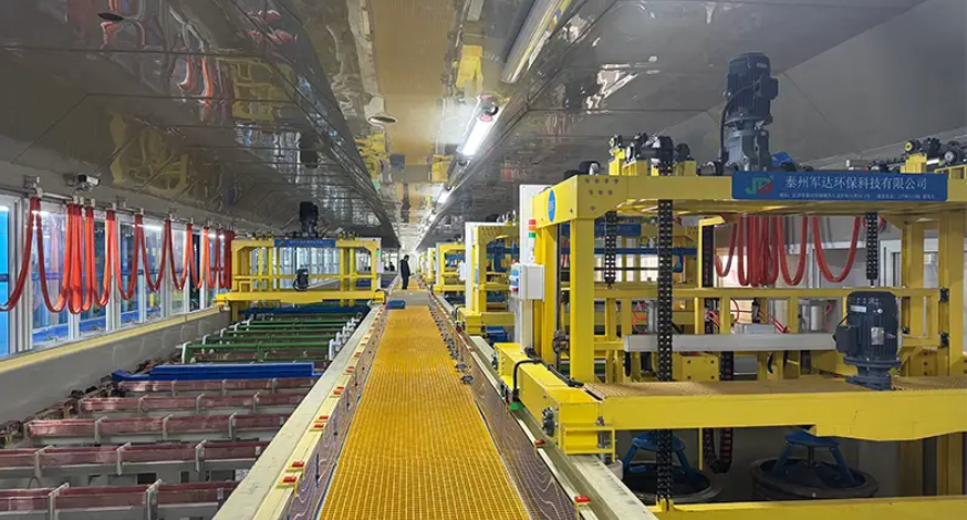
Dangler pressure rarely gets the attention it deserves until plating thickness starts drifting across a barrel load. Light contact creates localized resistance at the interface, so parts near the dangler tips plate faster while those further away lag behind. The result is a spread in zinc thickness that shows up most clearly on threaded fasteners and small stampings, where even a few microns of variation can affect torque or corrosion life.
Placement compounds the problem. If danglers sit too high or too low relative to the workload, current crowds through the closest layer of parts and leaves the rest starved. A slight downward angle and enough mechanical spring to maintain steady pressure during rotation keep the contact point from walking or arcing. Operators often notice scattered burn marks on parts near the dangler when pressure is too low, which is a late sign of poor contact rather than the root cause.
Getting consistent zinc deposition means treating dangler setup as part of the electrical circuit, not just a mechanical afterthought. Checking compression force, replacing worn tips before they flatten, and adjusting position for each barrel geometry all reduce variation. When pressure and placement are dialed in, thickness distribution tightens without slowing the line or adding extra plating time.
Additive Control in the Zinc Bath Stabilizes Plating Rates
In continuous galvanizing lines, plating rate fluctuations often trace back to uneven additive depletion in the zinc bath. Rather than relying on bulk bath temperature alone, operators increasingly monitor tracer elements like aluminum and nickel in real time. Small shifts in their concentration alter the interfacial tension between steel strip and molten zinc, changing how quickly the alloy layer forms. Holding these additives within a narrow band prevents the familiar thick edge defect.
The practical difficulty lies in the fact that additive burn-off is not linear. A line speed increase of ten percent may consume three times as much grain-refining agent, simply because the strip carries more fresh iron into the bath. If the control loop responds only to final coating weight, it lags behind the disturbance by several coils. Better results come from feed-forward dosing tied to strip surface area, combined with periodic bath sampling to correct drift.
Some mills have moved to closed-loop titration of aluminum with an optical emission probe mounted in the snout. This allows the control system to make small, continuous additions instead of large manual slugs. The result is a tighter plating window: coating thickness stays within ±2% of target across a shift, and dross formation drops because the bath chemistry no longer swings between excess and starvation. Consistent additive control thus does more than stabilize the rate—it extends bath life and reduces zinc consumption.
Gantry Speed and Barrel Loading Balance Immersion Time Across the Load
Achieving consistent immersion time across a fully loaded barrel requires careful coordination between gantry travel speed and the way parts are distributed inside the drum. When the gantry moves too quickly, the leading edge of the barrel enters the bath several seconds ahead of the trailing edge, creating a noticeable difference in contact time. Slowing the gantry down helps, but only if the load itself is balanced. A top-heavy or lopsided barrel can shift during lowering, causing one side to plunge deeper and altering the effective immersion profile even at a steady descent rate.
Practical adjustments often involve staging the load so that heavier components sit toward the center of the barrel, while lighter or more delicate parts remain near the outer edges. This reduces rotational sway as the gantry lowers the barrel into the tank. Operators then fine-tune the gantry speed to match the load's moment of inertia—dense, compact loads can tolerate a slightly faster plunge without losing uniformity, whereas bulky, irregular loads demand a slower, more controlled entry. The goal is to keep the barrel's orientation stable from the moment it breaks the liquid surface until it reaches full depth.
In many plating and coating lines, the immersion time window is narrow, often measured in single-digit seconds. A mismatch of even one second between the top and bottom of the load can produce visible thickness variation or incomplete coverage. By mapping the gantry's vertical speed curve against the barrel's fill pattern, technicians can identify the point where the load begins to rotate or tilt. Adjusting the speed just before that critical point—rather than applying a uniform slowdown—usually yields a more even immersion without adding unnecessary cycle time.
Anode and Rectifier Maintenance Prevents Coating Thickness Drift
Coating thickness drift usually starts with small shifts in current density, and those shifts often trace back to anode condition. As anodes dissolve over time, their effective surface area shrinks. The same rectifier setting then delivers higher current density to the remaining anode area, which can push plating rates above the target range. Routine anode cleaning, repositioning, and replacement keep the anode-to-cathode ratio stable, so the current spreads evenly across the part instead of concentrating in unpredictable spots.
Rectifier performance is just as critical. Dust buildup on cooling fins, loose bus connections, or aging diodes can cause the output to wander even when the dial stays put. A rectifier that drifts by just a few amps changes the deposition rate enough to alter coating thickness over a production run. Checking ripple, verifying voltage and current readings with a calibrated meter, and tightening connections during scheduled downtime catch these issues before they show up as rejected parts.
A simple log of anode condition and rectifier output creates a useful reference for spotting gradual changes. When thickness drift appears, comparing current readings with past records often reveals whether the problem is fading anodes, a rectifier in need of service, or both. Addressing both sides together keeps the plating process within its working window and reduces the need for constant manual adjustment.
Post-Plating Thickness Mapping Verifies Uniformity Before Parts Leave the Line
Operator runs a scanning probe over critical surfaces right after plating. The system builds a color-coded thickness map in real time, flagging any zones that fall outside the tolerance band. Thin spots show up immediately, so the line can be paused before additional finishing steps lock in the defect.
Instead of relying on spot checks or lab samples, this in-line mapping captures the full geometry of each part. High and low areas are documented with traceable data, and the map travels with the lot. If a drift in current density or bath chemistry starts creating uneven buildup, it's caught within minutes, not after a batch audit.
For complex shapes like connectors or heatsinks, this step has become the last visual gate before packaging. The operator sees the contour plot on the monitor and approves release only when the entire surface sits within spec. That closes the loop between plating parameters and outgoing quality, without slowing the line.
FAQ
A moderate speed, usually between 6 and 12 revolutions per minute, lets parts tumble without excessive impact. Too slow and the load stagnates, causing bare spots; too fast and parts can collide hard enough to damage plating or cause uneven current exposure. The exact setting depends on part geometry and barrel perforation, but staying in that range is a solid starting point.
The gantry’s lift and transfer motion, along with barrel tilt and immersion depth, affect how solution and current reach every piece. A well-designed system keeps the barrel fully submerged with steady agitation, prevents parts from clumping in one area, and allows uniform drainage between stations. If the barrel doesn’t rotate true or the hoist movement is jerky, you’ll see thickness variation from one side of the load to the other.
Zinc concentration, caustic level, and brightener balance directly determine deposition rate and grain structure. If the bath drifts, the coating can become rough, dull, or overly thick in high-current areas. Routine titration and additive replenishment keep the bath in a narrow window so every batch plates with the same appearance and thickness.
Regular checks on barrel contacts, dangler cables, and anode connections prevent resistance changes that lead to uneven current distribution. Cleaning barrel perforations, replacing worn gears, and verifying rectifier output also matter. Without this upkeep, a line can slowly drift out of spec and the operator may not notice until rejects appear.
Zinc anodes need to face the barrel from multiple angles so current reaches parts near the center as well as the outer layer. If anodes are concentrated on one side or too close to the barrel, high-current zones form and local plating becomes heavy. Spacing anodes evenly and adjusting the rectifier to the barrel’s surface area helps balance the current density across the entire load.
Common culprits include poor barrel contact, low solution level, insufficient agitation, and worn danglers. These create dead zones where parts receive little or no current. Fixing them usually means checking the electrical path, raising the bath level, adjusting rotation, or replacing contact points. Running a test panel or measuring thickness on sample parts helps identify which factor is responsible.
Using a thickness gauge on sample parts from each barrel, checking appearance under magnification, and tracking bath parameters in a simple log are practical. Some shops also run a small test coupon alongside production loads. This gives early warning of any drift in solution or electrical performance before a full batch is affected.
Look for a supplier that asks about your part mix, production volume, and plating specifications rather than pushing a standard package. They should provide barrel rotation options, reliable electrical contacts, and clear guidance on anode layout and bath maintenance. A supplier with process knowledge and responsive after-sale support makes it easier to hold tight coating tolerances.
Conclusion
Achieving uniform zinc plating on small parts in a gantry barrel line starts well before the rectifier is switched on. The perforation pattern in each barrel does more than allow solution exchange; hole size and spacing shape how current reaches the load. Too little open area starves the parts near the center, while oversized holes can let small components wedge and shield one another. Once the barrel is in the bath, dangler contact pressure and placement become the next critical variables. A loose dangler or one that sits too far from the bulk of the load creates a voltage drop that shows up as thin, patchy deposits. Operators who check dangler wear at every cycle and set contact points to match part geometry avoid most random thickness swings. In the bath itself, additive control does the quiet work of stabilizing plating rates. Brightener and carrier levels that drift outside the supplier's window change the deposit's grain structure and can speed or slow zinc buildup in ways that no amount of current adjustment will fix.
On the mechanical side, gantry speed and barrel loading directly affect how long every part spends at full current density. A fast transfer or an overloaded barrel shortens immersion time for the center of the load, producing underplated parts mixed with overplated edges. Balancing load weight against barrel capacity and setting a steady hoist rhythm keeps exposure even. Anode and rectifier maintenance matters just as much because pitted anodes or drifted rectifier output slowly move the whole line away from its target thickness. A weekly check of anode bags, connections, and ripple levels stops this drift before it becomes a rejected lot. Finally, post-plating thickness mapping closes the loop. Rather than assuming a process is stable, the company measures deposit thickness at multiple points on sample parts before they leave the line. That data feeds back into perforation choice, dangler settings, and additive dosing, so each batch gets closer to the same coating profile.
Contact Us
Contact Person: hayyr
Email: [email protected]
Tel/WhatsApp: 8613082110525
Website: https://www.jundaelectroplating.com