

China Curing Press Systems: Key Benefits for Modern Composite Manufacturing
2026-11-16
Composite manufacturers tend to focus on materials and molds, but the curing press is where inconsistency quietly creeps in. A small temperature spread or uneven pressure can turn an expensive layup into scrap. Modern China curing press systems are changing that calculation with better thermal uniformity, tighter pressure control, and automation-ready design. AUGU AUTOMATION brings these systems into sharper focus for teams that need repeatable results without overengineering the floor. Here’s a look at the key benefits now driving adoption in composite manufacturing.
Platen Flatness Stability Under Sustained Thermal Load
Sustained thermal load never acts on a platen as a single uniform temperature. The edges shed heat faster than the center, heating channels create their own repeating thermal signature, and every constraint point becomes a small anchor that resists natural expansion. Over days of continuous operation these gradients do not simply equalize; they settle into a pattern of internal stress. A plate that measured flat on a granite table after machining can gradually take on a shallow bow or a localized low spot once the working temperature becomes its actual rest state. In many cases the deviation is small at first, often under 0.05 mm across a meter, but it repeats in the same location each cycle and eventually becomes the new reference surface.
Time at temperature matters as much as the temperature itself. Cast iron and steel relieve residual stress slowly through creep and stress relaxation, so a platen that is stable during a four-hour trial can still drift over several weeks of production. The mechanism is rarely dramatic; it shows up as a gradual loss of contact pressure in one corner or a thin, persistent gap near the middle. Heating channel layout plays an overlooked role here because uneven spacing produces steady temperature bands that drive permanent deformation outward from the hotter zones. A more reliable approach is to rough-machine the platen, run a thermal stabilization cycle slightly above the intended working range, then finish-machine only after that stress-relief soak. This sequence lets the material move before the final flatness is cut into the surface rather than after.
Designing for long-term flatness also means accepting that the platen must be free to grow and shrink without fighting its supports. A single fixed reference point combined with sliding or flexing supports often holds shape better than a dense pattern of rigid bolts, because every fixed point becomes a bending moment as temperature expands the metal. Inspection should be done at the actual process temperature whenever possible, or at least recorded at a consistent point in the thermal cycle. Cold measurements hide the real condition of the surface; a platen can return to near-perfect flatness when cooled yet still run with unacceptable distortion under load.
Pressure Control That Adapts to Part Thickness Changes
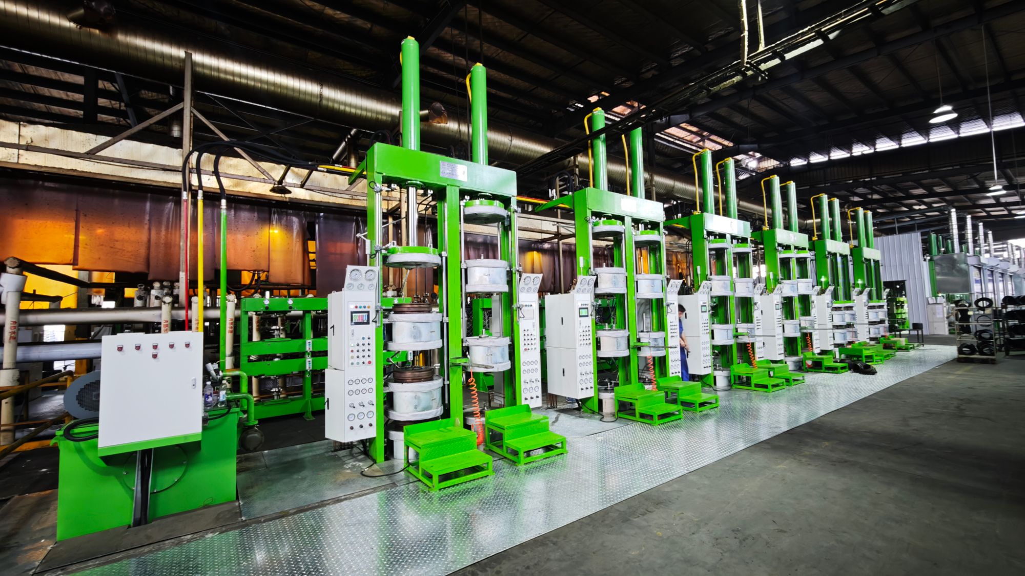
Part thickness rarely stays exactly where the setup sheet says it will. Coil tolerances, thermal growth, and upstream forming variation all shift the stack-up by a few hundredths of a millimeter, which is enough to turn a stable pressure setting into an over- or under-loaded condition. Instead of relying on a fixed command, the control compares actual force feedback against a moving reference and adjusts the valve or servo command every few milliseconds. That keeps the working pressure matched to the surface being processed, not to a nominal value that may no longer exist.
The adaptation logic doesn't need to know the exact thickness in advance. It watches the force build-up curve, detects the moment contact stiffens, and modulates pressure so the tool follows the part rather than fighting it. On thin sections, the loop backs off early to avoid marking or deflection. On thick sections, it allows a steeper rise so full contact is reached without a long dwell. The result is a pressure profile that changes shape with each part, while staying inside the limits set by the process engineer.
Mixed-batch production is where the difference becomes obvious. Material stacks shift from skid to skid, and the control handles that variation without a recipe change or constant manual correction at the HMI. Maintenance teams also see fewer pressure-related faults because the loop is no longer pinned to a single target. Over time, the logged force curves reveal thickness drift sooner than a pass/fail inspection would.
Lower Idle Energy Draw During Multi-Cavity Curing
Most curing systems pull nearly the same power whether they are actively cycling every cavity or just sitting between shots. That idle draw is easy to miss because it never appears in cycle-time charts. On multi-cavity setups the gap becomes more obvious: pumps, heaters, and control loops stay spun up even when only one cavity is being loaded, cleaned, or inspected. Lowering that baseline means the equipment only burns serious energy during the actual cure window instead of dragging it across the whole shift.
A practical route is staged idle logic that drops holding pressure and backs platen temperature down after a short delay, then restores conditions fast enough to avoid slowing the next shot. On systems with shared hydraulic or vacuum circuits this also cuts heat rejection into the work area, which can make cavity-to-cavity consistency easier to hold. The per-cycle difference looks small, but it adds up across hundreds of partial cycles, operator breaks, and overnight standby periods.
Faster Mold Changeovers Without Realignment Delays
Shaving minutes off a mold swap usually comes down to eliminating the hidden pause between unlocking the old tool and locking in the new one. Many shops still rely on visual checks or manual dowel alignment, which invites tiny offsets that compound into scrap or rework. Instead of treating alignment as a separate step, consider building a locating system that repeats within a few microns from the first clamp to the last — ball-lock receivers, tapered guide pillars, or dedicated zero-point plates can do the heavy lifting while operators focus on hose and sensor connections.
One practical shift is to move setup verification away from the platen and into the offline staging area. Pre-stage the next mold on a cart with pre-set ejector strokes, pre-wired thermocouples, and pre-measured clamp heights. When the changeover begins, the tool slides in on rails or rollers, seats against hardened stops, and the clamp sequence finishes without anyone reaching for a pry bar. This turns a 45-minute alignment struggle into a predictable 12-minute exchange, even on older presses.
The real gain shows up in the shift log, not just the stopwatch. Fewer alignment delays mean less thermal drift from a cooling barrel, fewer first-shot defects, and less wear on locating bores. Crews stop dreading the “difficult” molds because the process no longer depends on a single experienced hand nudging things into place. The result is a changeover rhythm that holds up under production pressure, letting the next job start clean instead of limping through the first hour.
Hydraulic Circuit Design That Avoids Pressure Spikes
Pressure spikes don't usually announce themselves until a fitting weeps or a hose gets yanked, and by then the root cause has been building for months. In circuits where a directional valve shifts hard or a loaded cylinder reaches end of stroke, the column of oil can decelerate almost instantly, converting kinetic energy into a pressure wave that far exceeds relief settings. A practical fix is to slow the rate at which flow changes rather than trying to contain the spike after it forms. Proportional valves with adjustable ramp times, pilot-operated shift sequences, or simple orifice-restricted pilot lines give the fluid a brief escape path during the transition, so the pressure trace rounds off instead of peaking.
Accumulators, especially small gas-charged bladders, work best when placed close to the source of the transient, not just somewhere along the main gallery. Their effectiveness drops quickly if the connecting line is long or the pre-charge is set blindly. It helps to tune the pre-charge pressure below the minimum working pressure but high enough that the bladder doesn't fully collapse during normal operation; otherwise the accumulator becomes little more than a dead-end chamber. In circuits with over-center loads or regenerative flow, an anti-cavitation check or a controlled bypass around the actuator can smooth the transition and keep return-side pressure from spiking when flow reverses.
Relief valves still matter, but a spike can outrun a direct-acting relief at high flow if the passage to the valve is restrictive. A pilot-operated relief with low hysteresis and a short, generously sized discharge path reacts more predictably. The goal is to design the circuit so the relief never has to absorb high-frequency transients alone. Some designers rely on pressure-compensated logic elements or pre-fill valves that decompress the trapped volume in a metered way before opening fully. Combined with correct hose expansion margins and a layout that minimizes long, rigid columns between the pump, valves, and actuators, those choices turn a harsh pressure event into a controlled pressure change.
Operator-Level Controls That Reduce Setup Errors
Setup errors rarely come from carelessness alone; they often start when an operator has to interpret a drawing, pick the right insert, or manually key in a wear offset under pressure. Simple operator-level controls shift the burden from memory to physical or visual constraints. Color-shaded setup sheets, tool carts arranged in sequence, and barcode checks against the work order make the expected condition obvious before the cycle starts. In many shops, a first good part checklist is pinned at the load station, with the operator signing off only after measuring two or three critical dimensions.
Digital controls can reduce the remaining guesswork. Machine prompts that verify program number, fixture ID, and tool assembly before the door locks help catch mismatches at the moment they happen. Tool presetters that send offsets directly to the control remove transcription errors, while probe routines check stock size, vise location, or tombstone orientation without relying on the operator's visual judgment. These are not inspection add-ons; they are setup steps built into the normal sequence.
The most effective controls are almost invisible. A torque wrench that clicks at the right clamp pressure, a locating pin that only fits one way, a chip cover interlock that prevents starting with the wrong guard position — these reduce the number of decisions an operator has to get right. When operator-level controls are designed this way, they don't just catch mistakes; they make the correct setup feel like the path of least resistance.
FAQ
They pair heavy-duty frame construction with multi-zone heating and closed-loop pressure control at a cost that lets mid-sized manufacturers upgrade without overspending. The better systems are built around modular hydraulic units and PLC interfaces, so cycle recipes can be changed quickly for prepreg, SMC, or resin-infused parts.
Independent heating zones with PID tuning and thermocouple feedback near the tool surface matter more than a single impressive specification. A practical target is uniformity within plus or minus two degrees Celsius across the working area during ramp and soak, which reduces hot spots that can distort thin laminates or cause uneven resin flow.
Repeatable pressure keeps fiber volume fraction consistent and helps drive out trapped air during the cure cycle. With closed-loop servo or proportional valve control, operators can hold pressure within a narrow band and program step changes for breathing cycles, which lowers void content and improves mechanical properties.
Yes, most suppliers offer a range of platens, daylight openings, and tonnage options, along with heated or cooled zones matched to the tool layout. Some also add vacuum chambers, quick-change mold carts, or data logging packages so the same press can handle prototype work, low-volume aerospace parts, and larger automotive panels.
Current systems often include recipe storage, barcode or QR scanning for part traceability, and remote diagnostics through industrial networks. Operators can monitor ram position, temperature curves, and pressure trends in real time, then export batch reports for quality documentation without manual transcription.
Many newer Chinese systems use variable-displacement pumps, servo drives, and better insulation around the platens. This allows the press to hold pressure without running the motor at full load and to retain heat between cycles, which lowers electricity consumption during long cure profiles and reduces heat loss into the shop.
Clean hydraulic plumbing, easily accessible filters, and hardened platen surfaces reduce downtime. A good system should include self-diagnostics for oil temperature, filter condition, and seal wear, so maintenance can be scheduled before a failure stops the line.
Aerospace, automotive, wind energy, and sporting goods all use this class of press for products like carbon fiber panels, battery enclosures, leaf springs, and bicycle components. The main advantage is the ability to hold precise heat and pressure over long cure cycles while still supporting fast changeovers for mixed production.
Conclusion
Modern composite manufacturing in China has shifted toward curing press systems that hold platen flatness even when thermal cycles run long, which directly reduces the risk of uneven resin flow and part warpage. Rather than forcing operators to compensate for drift, the press frames and heated platens are built to stay dimensionally stable, so repeat jobs come out closer to the original tooling assumptions. Pressure delivery is equally important: instead of fixed force settings, these systems sense thickness changes as the material settles and adjust output without overshooting. That adaptive behavior keeps laminate consolidation consistent without the sudden hydraulic spikes that often damage fragile tooling or embedded inserts.
At the production level, multi-cavity operations benefit from lower idle energy draw when platens are holding temperature between cycles, and mold changeovers happen faster because clamping and guidance features reduce realignment work. The controls are organized around operator actions rather than buried engineering parameters, so setup mistakes drop without relying on lengthy training. This matters most in high-mix shops where different part thicknesses and tool heights move through the same press in a single week. Across a shift, these improvements shorten downtime, reduce scrap from pressure fluctuations or alignment drift, and make it easier to run mixed part families on the same line without constant manual correction.
Contact Us
Contact Person: Lareina
Email: [email protected]
Tel/WhatsApp: +86 17561696737
Website: https://www.auguauto.com/